
A large number of lines controlled by our company are prototypes with respectively different topology and various equipment, e.g. consumers and sensors. However, hardly any modification of the source code is necessary for the adaptation of the control. The reason for this is simple: our system is already well thought out, modularly designed. Modifications and adaptations are parameterized, but programmed only in exceptional cases. This saves time and creates reliability – for the customers benefit.
MCR module (measuring, controlling, regulating)
The MCR module is responsible for all basic measuring, controlling and regulating tasks. These are combined as a module and delegated to an independent application – the peripheral computer control program. In addition, the peripheral computer control program runs on a separate computer. Once equipped by the control computer with data and orders, this module regulates process variables, records, processes and displays measured values, executes transport processes and controls drives independently and without further interference of the main computer system. This way, all process parameters are safely maintained during updates, maintenance measures or switching-off of the main computer system since the involved control circuits will not be interrupted. Thus, main computer capacity is spared for production and process control as well as for handling the man-machine interface.
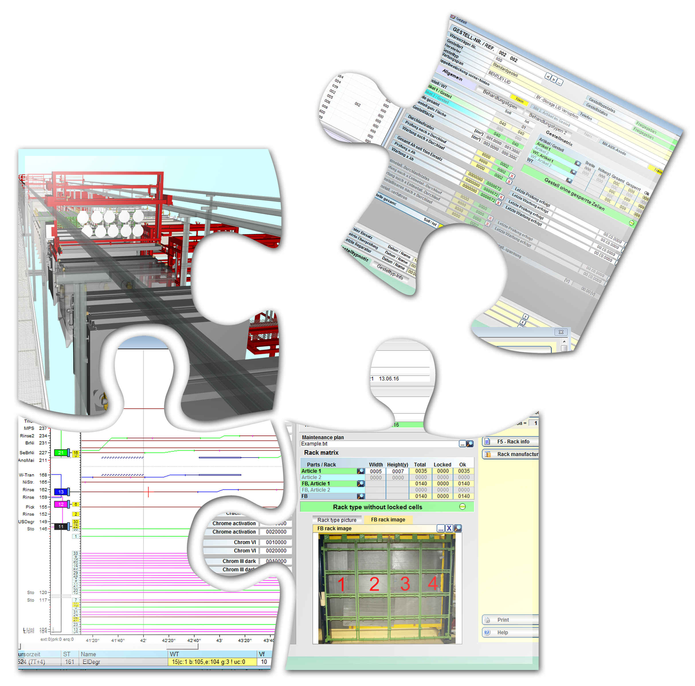
Visualization module
This module comprises a vivid and intuitively to be operated user interface. In the present standard version as 2D system, the operator is provided a realistic display of all plant components. This way, the line state, e.g. distribution and type of the material in the line, all transport movements and the switch state of all aggregates can be viewed at a glance at any time. As default, I/O state display and signal state tables of all individual components are integrated. Additionally, a 3D visualization interface is available, particularly displaying in a realistic manner peripheral handling units and transport equipment incl. mechanical couplings and mobility levels. In this display mode, all control tools already familiar in 2D visualization are available and are supplemented by vivid and descriptive maintenance instructions. Source of the control signals and the way of their generation is also vividly presented. Thus, detection of error causes is made easier and sped up. Consulting the manual and scrutinizing the construction drawings can be spared in most of the cases since the control contains a completely realistic model by means of which it is possible to draw the necessary conclusions.
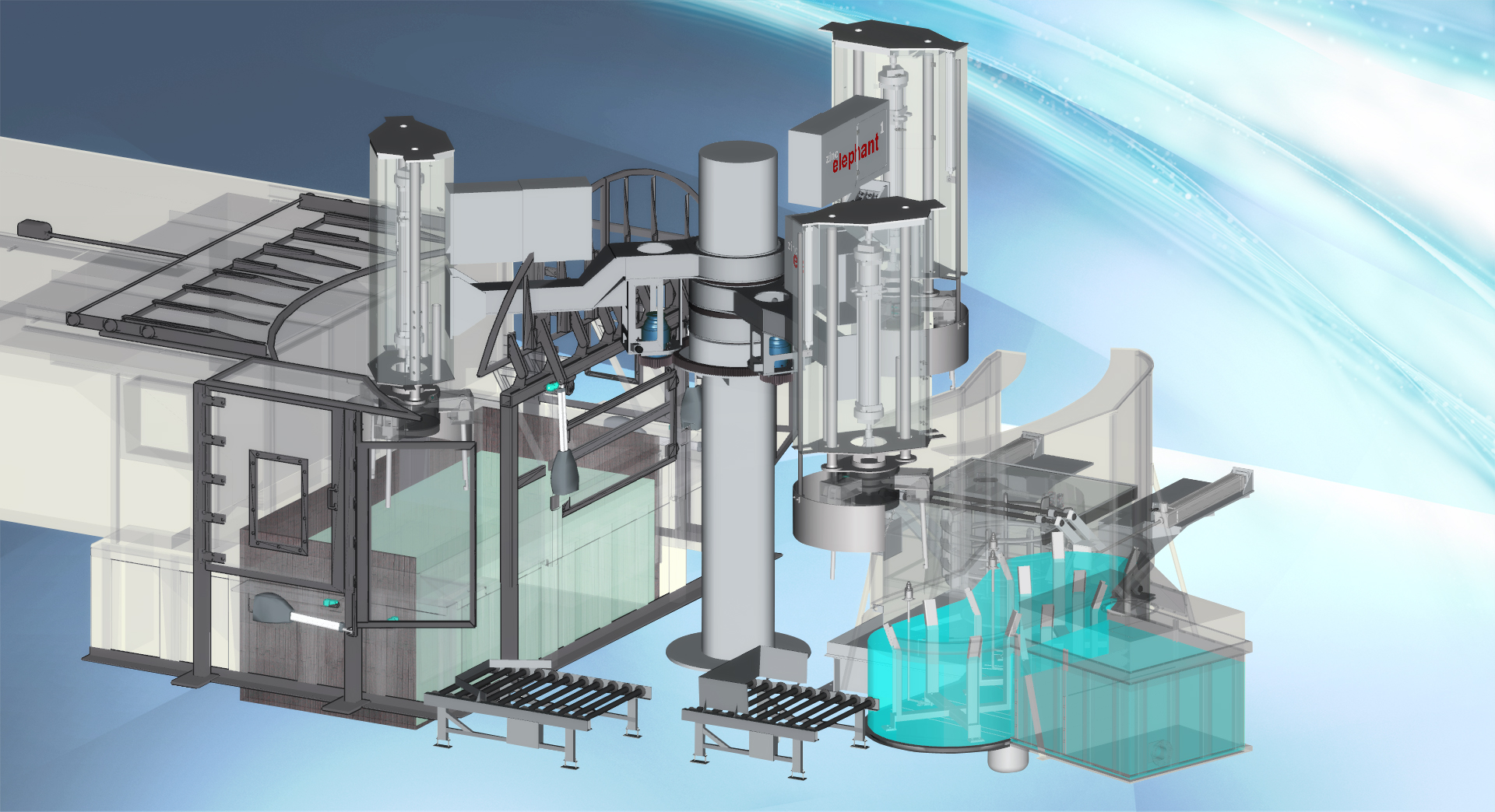
For many years, we have been using our visualization to offer the user a realistic impression of the three-dimensionality of the objects and parts of the line to be controlled. This is reached by a perspective presentation plus some other tricks of representation techniques. We call the result 3D display in order to clearly stand out from the usual, completely flat representation in quite a number of visualization surfaces.
Further development of our visualization also offers the three-dimensional representation of the involved objects; however, with freely selectable viewing positions and viewing directions. In addition, most objects are designed exactly according to the construction drawings concerning their coupling to other objects. This is a good reason to raise this further development of our visualization system to a 3D+ system.
Process control module
The process sequence control module with different approaches realizes the implementation of the set sequence of process steps (process follow) into a matching sequence of transport commands to the transport equipment. FLS stands for a system for automatic implementation of a time-way diagram into a sequence of transport instructions. TLS stands for a system for automatic implementation of a set process sequence into a sequence of transport instructions.
AMT is one of only few manufacturers who have perfected and extended the drive sequence control system (FLS) so that a generated TWD (time-way diagram) can directly be loaded into the computer system for processing. This is done at program modifications without further commissioning work directly via remote service at the customer.
Continuous recording of all process steps of the transport equipment at any time allows analysis in case of error, at throughput losses or cycle time violations; thus, permanent traceability is guaranteed.
Both systems chose the transport processes to be executed in consideration of the product mix; e.g. the combination of different processes in the same production interval, and in consideration of the human factor; e.g. fluctuations of the equality of loading releases and of all relevant technical data of the plant. By help of TLS, the operator can implement own programs and program variants in a short time. Process supply created on the basis of a time-way diagram can serve as starting point for the creation of program variants. This way, a functional starting point with sound throughput is created that can be used for step-by-step execution of process-related adaptations.
Production planning module
This module comprises the complete order management, article library, rack management incl. technological history, rack observation and notification of rack maintenance cycles, rack graphics incl. the display of faulty and blocked clip-on positions, and barrel management analogous to the rack management. Production scheduling means the organization of the material flow through the plant, the combination of flightbar, barrel or partial charge sequences optimal for throughput and quality, and the management of required and actual production quantities. At bulk material, optimal batch distribution is determined in consideration of production time, current consumption, and article-specific settings for the barrel weight. An integrated residual quantity optimization prevents the occurrence of technologically non-producible residual quantities.
Throughput optimization module
Optimal determination of the entry sequence is of particular importance for the throughput. The respectively next flightbar is determined on the basis of the available material supply or stock of orders, within the time interval defined by the cycle time. This also works without storage stations. In case the required quantities to be produced were previously entered into a so-called material supply list, so the system determines which flightbars with which articles will be consecutively released in order to optimally process the order quantities. Order data can be entered manually or adopted automatically via a data interface to the customer’s internal PPS system.